Iris Split Mechanical Keyboard Build
A blog about my experience building my first split mechanical keyboard.
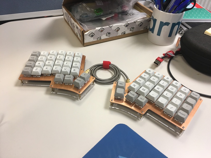
I’ve been experimenting with ergonomic set-ups and the wonders of mechanical keyboards, and so I decided to build my own!
In this blog I’ll talk about my experience building my first mechanical keyboard. I’ll cover my aims (and constraints) for the build, followed by a build log, before finishing with some comments and further work.
But first a handy link:
- Iris Mech Build Repo for Everything related to this Build
Aims, Constraints, & Components
Aims
I’m at that stage of my career where I’m starting to optimise my work-flow so I can focus on the tasks that need the real attention. This ranges from using vim macros to handy scripts, however standard keyboards are incompatible with these kinds of tricks as it still requires as much work to invoke them. I’ve been using a Vortex Race 3 as my daily driver which partially bridges the gap with programmable macros, bindable keys, and stock layouts that make typing more efficient; however it is not fully reprogrammable to the n-th degree. That is, It doesn’t have arbitrary macros that can invoke arbitrary programs, with arbitrary symbols bound to keys, and an arbitrary number of layers I can switch out as needed. I’d like a keyboard that can do this without hindering my flow.
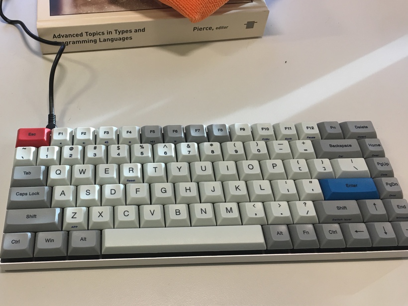
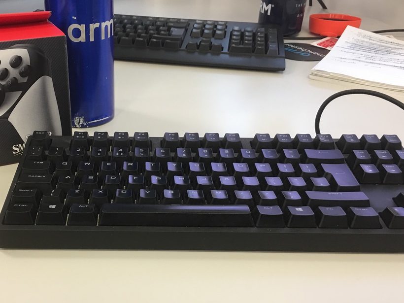
I spend a lot of time at my desk typing on a fixed board and so I’d like to mitigate the long-term effects of RSI. I’ve been looking into stand-up desks, better ways to work, and the ergonomic things I can do to mitigate negative effects of, in essence, cramping up over a desk due to extended use. Standard keyboards force your hands to a small fixed-point of the table when working, and this is not a natural position for your hands. I’ve seen the effects of long term cramping over a career and I aim to avoid the same result. I have used several non-standard boards with different mechanical switches including my Vortex (MX Clears), a Roccat Ryos MK Pro (MX Black), a Filco Ninja Majestouch 2 (MX Brown), Apple Magic keyboard (Butterfly switches of doom), a Das model S (MX blues), and others. All of these models are fixed, and so the next logical step is to consider split keyboards. My colleague Alastair wrote a great blog about his split build: he designed his split board to sit on top of his MacBook Pro. This is a good build, however split builds like these are still bounded by the fixed-point problem and fiddly to get right as you must find the right angle of split before you make the board. Instead I aim to build a board which is essentially cut in half so I can adjust the angle of use as much as I need. This seems like a general solution to the fixed-point problem and there are several builds out there that do this well.
Constraints
I only have a week to build this board and any related components, such as firmware. This means the build should be well planned out, and more importantly actionable within the time I have. So some of the components such as the PCB will likely come pre-made to make this build possible. Fortunately we have a maker lab at work stocked with the latest and greatest in technology from laser cutters to 3D printers and so resourcing the tooling shouldn’t be an issue. This does however mean I need to ensure all the components arrive before I start the build, which may take some time if they are custom components.
Second, I need to consider the factors of an ergonomic build that will improve my work-flow as these will likely inform the kind of build I make. The first consideration is the kind of switch and the actuation force required to press them. I tend to prefer tactile switches with heavier actuation forces such as the Cherry MX clears. Tactile switches have a noticeable activation point for good touch typing whilst being office friendly (not loud). The choice of switch will likely have an effect on the switch plates I can mount them to, the PCBs that support them, and an onset of other side effects for the build (such as build height, usable keycaps, and more).


Another important consideration is how many keys I use on a daily basis. As an engineer I make use of many special characters and short-cuts, however none of these are supported by larger full-size (100%) boards by default. Further I don’t use most of the keys on standard size boards, and this adds travel time for the rare occassion I do. Tenkeyless (87%) boards improve this with less keys, however I find there is still unused keys and time wasted moving my hands to or from the home row. My vortex at 75% hits a sweet spot of key use-density, quality, and size; however it is not split and has limited programmability of macros and key-bindings. I am yet to try a smaller (40-50%) board, such as the planck, but my suspicion is that this won’t be good for my large hands. This suggests I may prefer I mid-sized board with a higher number of modifiers and layers within range of the home row.
At this point in the build process I did some research to get an idea of how mechanical keyboards work, and consider which components would be best for me. Here is a quick list of useful links you may find useful:
- Special mentions go to LinusTechTips, TAEKeyboards, and RhinoFeed which are a good start as any for somebody to get into mechanical keyboards.
- The Chyrosran77 Youtube channel had some particularly interesting insights into the history of key switches and keyboards which made for some good binge watching.
- Mechanical Keyboards Subreddit: It almost goes without saying that this is one of the best resources for finding information about mechanical keyboards. The guides go into a lot of detail and Google almost always bought me here.
- The anatomy of a board: This guide by a Microsoft engineer is a particularly detailed account of how each of the components of a board work.
- WASD keyboard guide: This guide was useful in describing the differences between the popular brands of mechanical switches and the peripherals (like O-rings). This was further complimented by Reddit.
Components
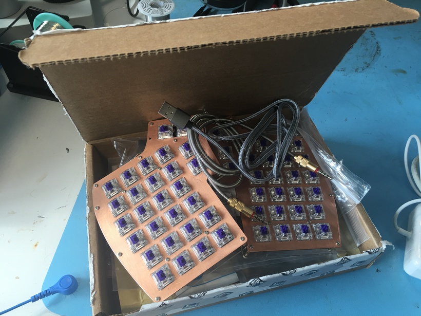
Now the research phase is over and the components have arrived, we can look at the components in detail. As is self-evident by the title I settled on an Iris split keyboard with a brushed copper switch plate, Zealios v2 67g tactile switches, and DSA profile PBT plastic keycaps in an off-white/grey. As for the style, I am going for an industrial look with a copper main and metallic accents. Combined with green LEDs the goal is to give a copper patina look but without the patina. For firmware I went with the Quantum Mechanical Keyboard (QMK) firmware due to its ubiquity, ease of use, and time constraints on this project. Let’s look into the iris PCBs first to set the stage on why I went with this form factor.
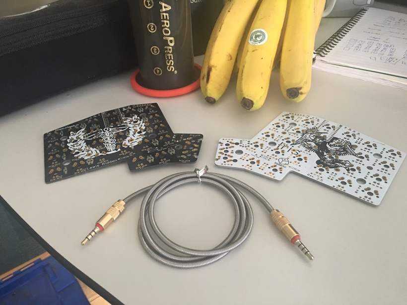
When choosing a split I had plenty of choice including the Ergodox, Iris, Let’s Split, Helix and more. The Ergo family seemed to be slight too big / too much going on for me; this would increase finger travel time when working. Conversely Let’s Split and Helix families of boards were slightly too small and I wouldn’t make full use of my thumbs. An alternative was the Helidox design which solved this problem, however I was not keen on the exposed boards on top. Instead I went for the Iris which struck a sweet spot between utility and size as well as having fashionable designs around. Additionally there are plenty of Iris build guides, which is valuable given the time constraints of this build (here, here, here).
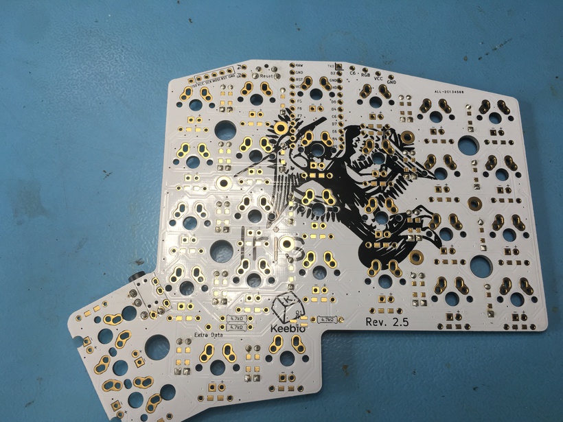
Keeb offer multiple kinds of PCB but their most recent incarnation, the Rev 3, was the only one in circulation. I wasn’t a fan of this design as it already had many of the components pre-soldered on. I wanted to learn about soldering and working with these components myself so I had to find some old stock. The result of this search is a pair of B-stock boards of different colours; whilst this isn’t symmetric, it is still pretty. The choice of PCB informed the rest of the design and in particular the switch plate.
My custom switch plates have arrived for my mech build, thanks @LaserBoost! pic.twitter.com/vUWUVVsQIL
— Luke Geeson (@LukeGeeson) June 30, 2019
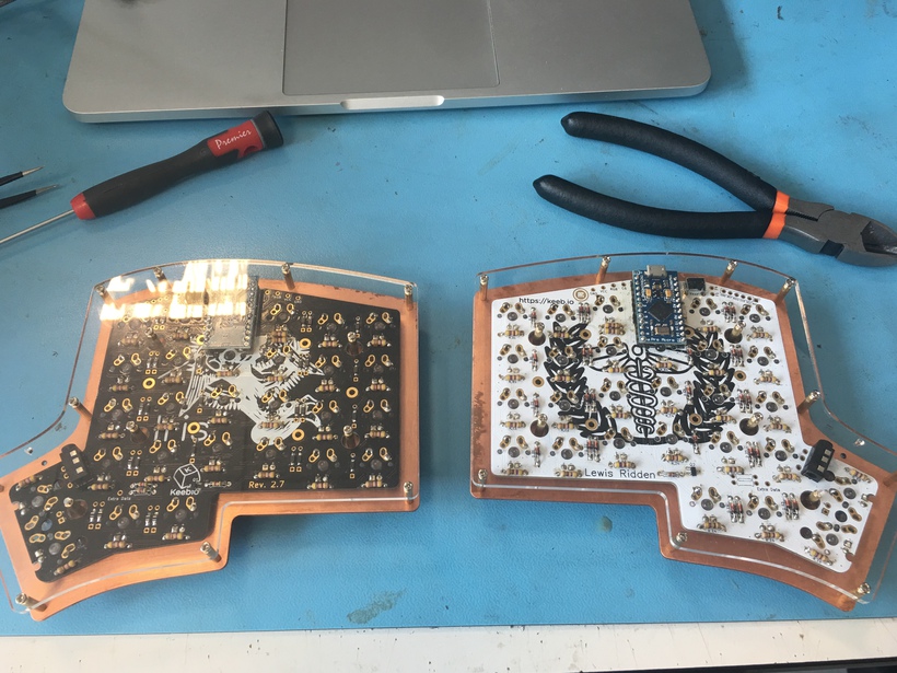
Next I had to consider the aesthetics of the board, notably by choosing a switch plate. On one hand I wanted something practical with no flex, but on the other hand it had to look nice (as all custom boards must!). I settled on a metal plate as this would stabilise the typing surface and the mount onto which the PCB was fixed. I went with copper after settling on an industrial (but not quite cyberpunk) look. I went with an open-side design and an acrylic base for the board so I could show off the circuitry underneath.
My key switches for my custom mech build have arrived, thanks @ZealPC! pic.twitter.com/KMKHHrMvYu
— Luke Geeson (@LukeGeeson) July 3, 2019
Next up was the choice of switches. I wanted something tactile but I’m not a fan of Cherry MX browns (it feels like standing on slugs) and I use MX clears in the vortex. Popular switches at the time included Zealios v2, Holy Pandas, Kailh Box Royals, or variations of Alps. I went with Zealios v2 67g as they are known for the tactile bump at the top of the switch, the solid design, and MX compatibility with the other components. Realistically switch choice should have governed the choice of switch plate and PCB, and in the next build it may, but for the first build I wanted something familiar.
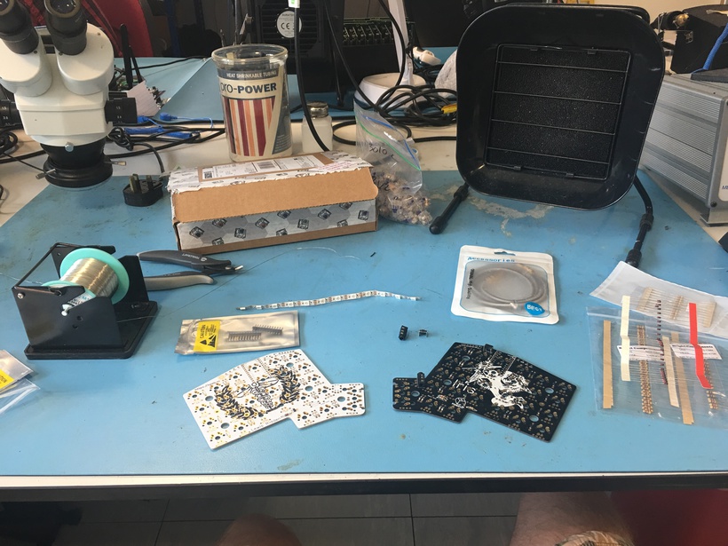
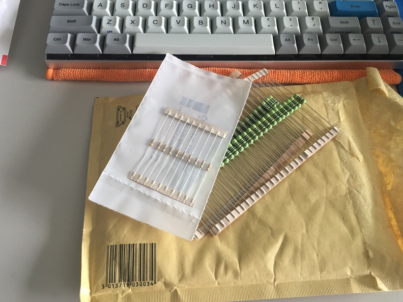
The last main component was the key caps, I chose to go with DSA profile dye-sublimated keycaps from signature plastics. I wanted a profile that could help me navigate to the home row, whilst having a quality sound and feel that wouldn’t distract me at work. I played it safe and emulated the vortex colour scheme of off-white and grey caps (GEK and GKK). The rest of the components include: a silver TRRS cable with silver sheaf, Pro Micro (and now an elite C) micro-controllers, green 1.8mm LEDs, resistors for the LEDs and switches, diodes, nickel plated M2 stand-offs, and a strip of green LEDs for under glow.
Build Log
With the components ready to go, it was time to build the board. The process followed roughly the following steps:
- Test the components to ensure they work.
- Lacquer the unfinished copper on the switch plate.
- Solder the resistors, TRRS jack, and diodes onto the PCBs.
- Mount the switches onto the plate and PCB.
- Solder the LEDs and micro controllers onto the PCBs.
Each of the following subsections cover these.
Test the components to ensure they work
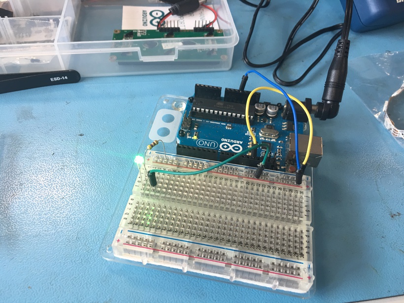
First I tested that the LEDs, the micro-controller, and the switches operated as expected. To test the LEDs I rigged together a simple circuit using a 5V rail from an Arduino, a resistor, and an LED. I simply tested that the LEDs turned on.
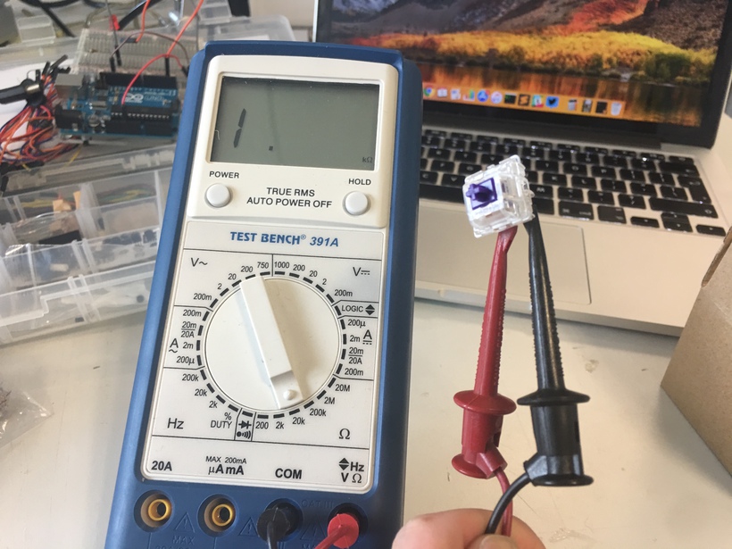
Next I tested that each of the switches worked as expected, I used a multi-meter to measure the current across them. No surprises here.
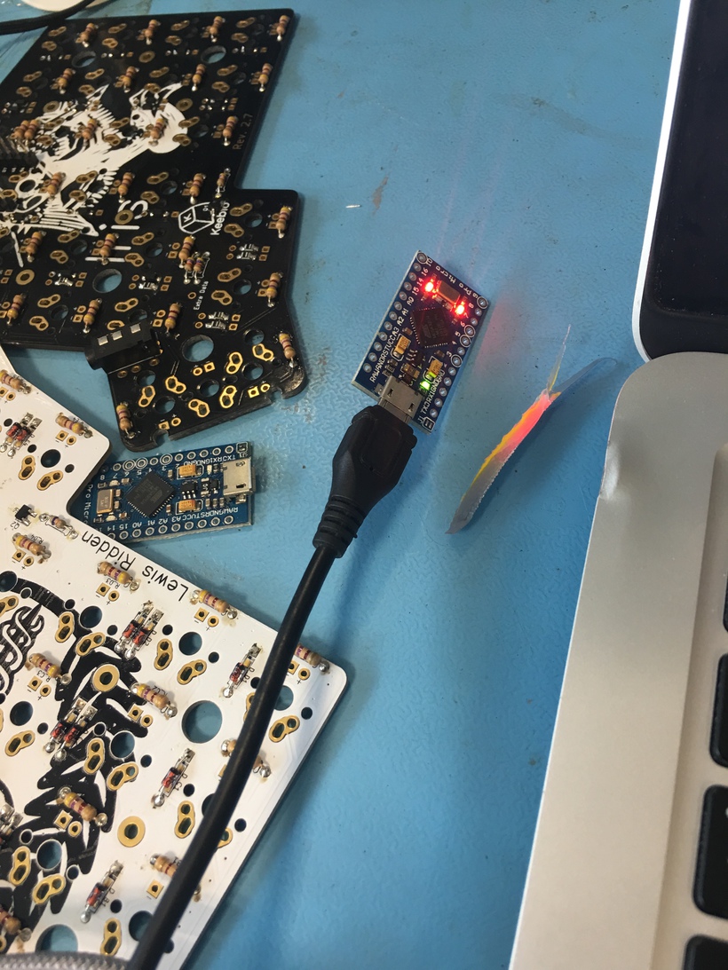
Next I tested that the micro-controllers were not dead on arrival and installed the firmware. I couldn’t test the actual functionality at this point until everything else was done, which is annoying but unavoidable. This involved cloning the firmware from GitHub, and later QMK toolbox. I had some trouble with this due to some avrdude related issues using an incompatible version of gcc to compile the key-mappings. I also could not run make keebio/iris/rev2:default:avrdude to flash the default key-mappings onto the micro-controllers as this required a two-stage reset and fiddling with the dodgy Caterina bootloader. In the end I installed qmk toolbox and let that do the work.
Lacquer the unfinished copper on the switch plate.
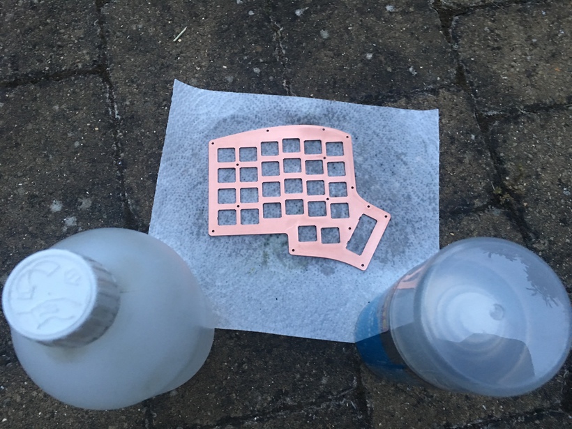
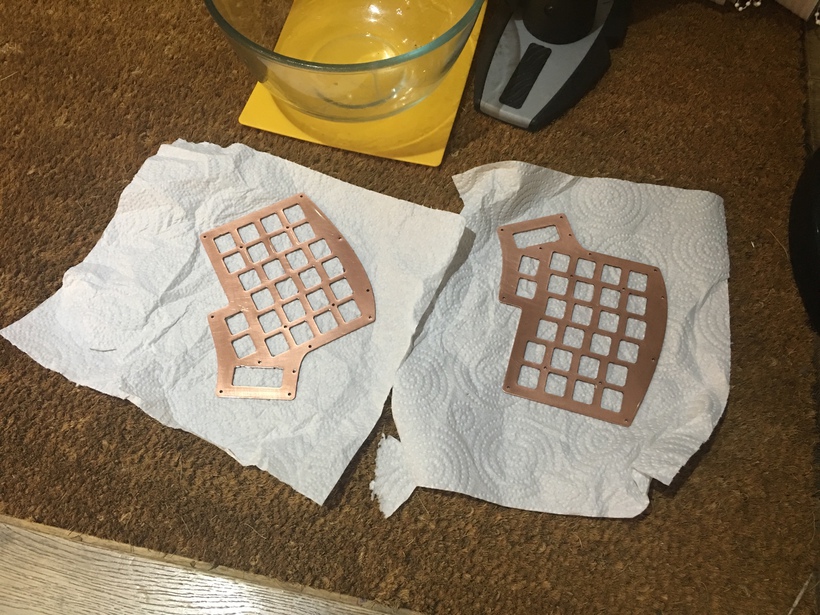
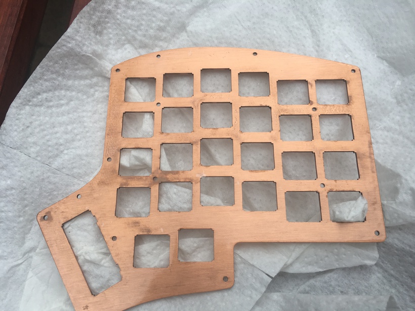
The copper plates I received were not finished. I wanted to preserve the beautiful gleam of the copper for as long as can and so I lacquered the plates. This was perhaps the most unpleasant part of the build, but I’ll get into those later for the sake of narrative. To lacquer untreated Copper you need the following:
- A clean dust free area with plenty of ventilation.
- knowledge of the materials you are working with including metal lacquer.
- Plenty of time and patience.
I had one of these to begin with. To lacquer Copper you must first clean off any dust or dirt using something that doesn’t leave a residue like Isapropyl Alcohol. Next you must apply the lacquer consistently across the plates, making sure the plates are flat so the lacquer doesn’t travel to one side. Then the waiting game begins as you must keep an eye on this to ensure no dirt settles on the sticky surface, and reapply a new coating every 15 minutes or so. Do not leave it 24 hours to re-apply in hot conditions as this will cause the lacquer to flake off, and you do not want to have to clean it off!
Solder the resistors, TRRS jack, and diodes onto the PCBs.
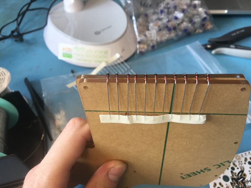
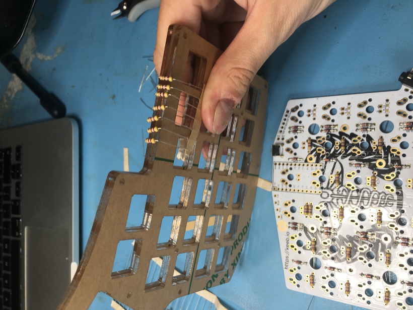
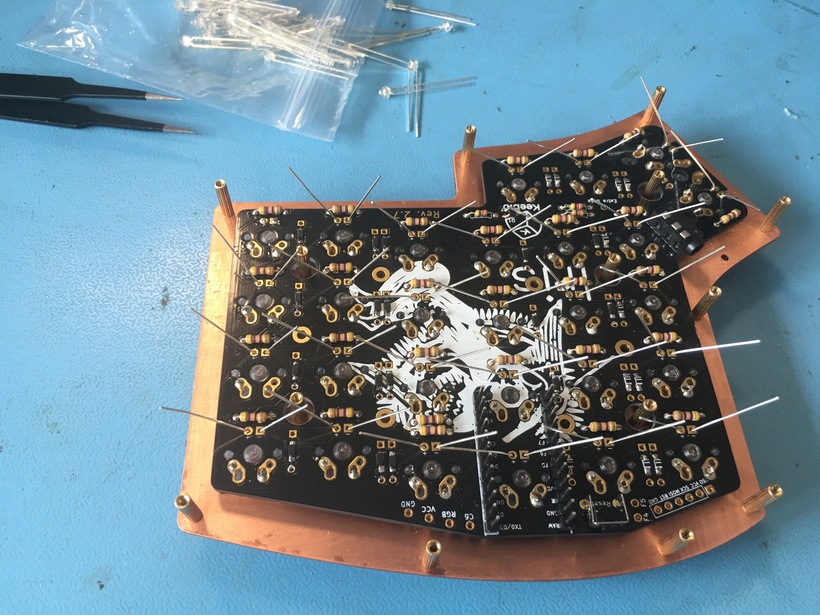
Next I had to prepare the through-hole diodes and resistors to solder to the board. To get a consistent fold, I used the acrylic base as an edge against which to fold the components over.
Followed by careful placement.
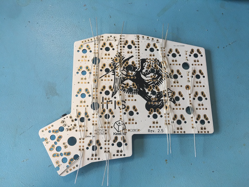
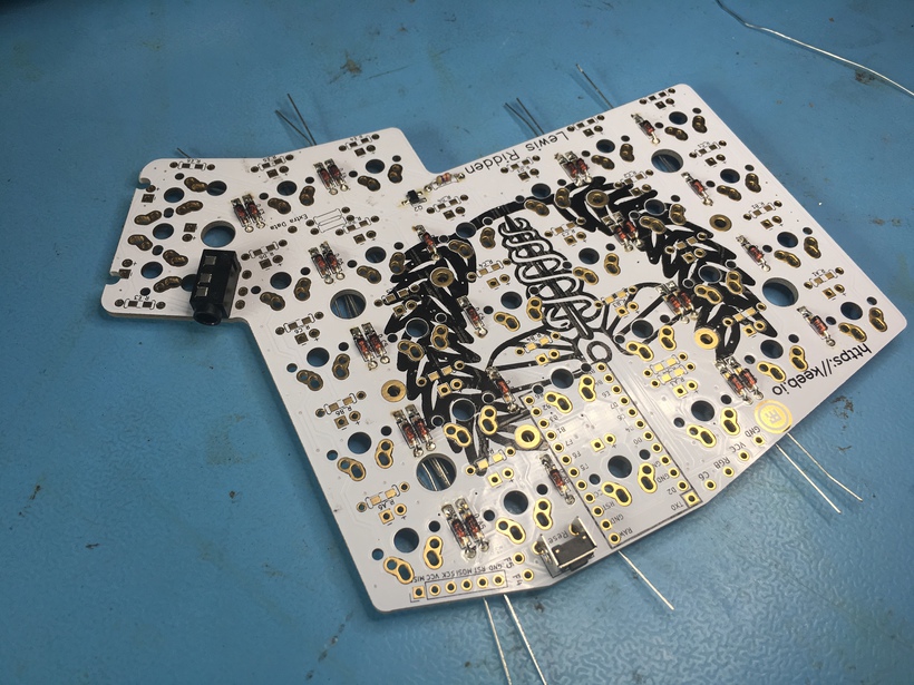
And finally soldering.
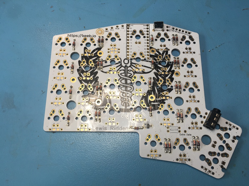
This process was repeated for the resistors too.
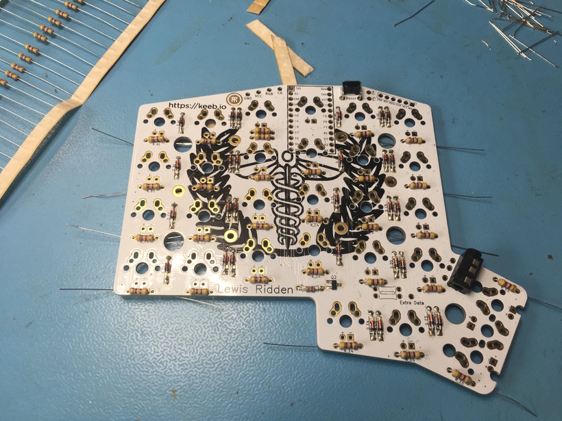
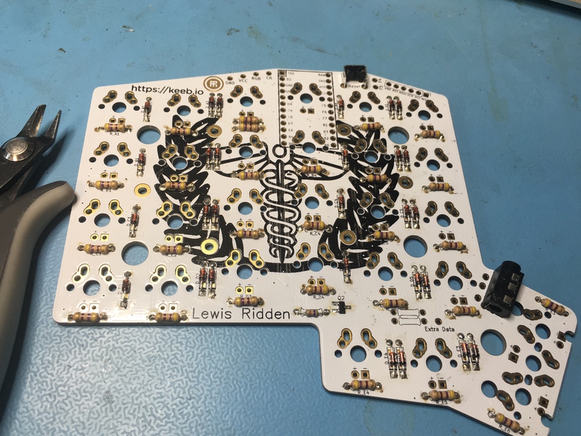
It’s worth checking at this point that you haven’t got any dry joints which may cause your board not to work later if the contacts aren’t connected.
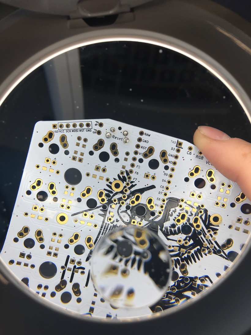
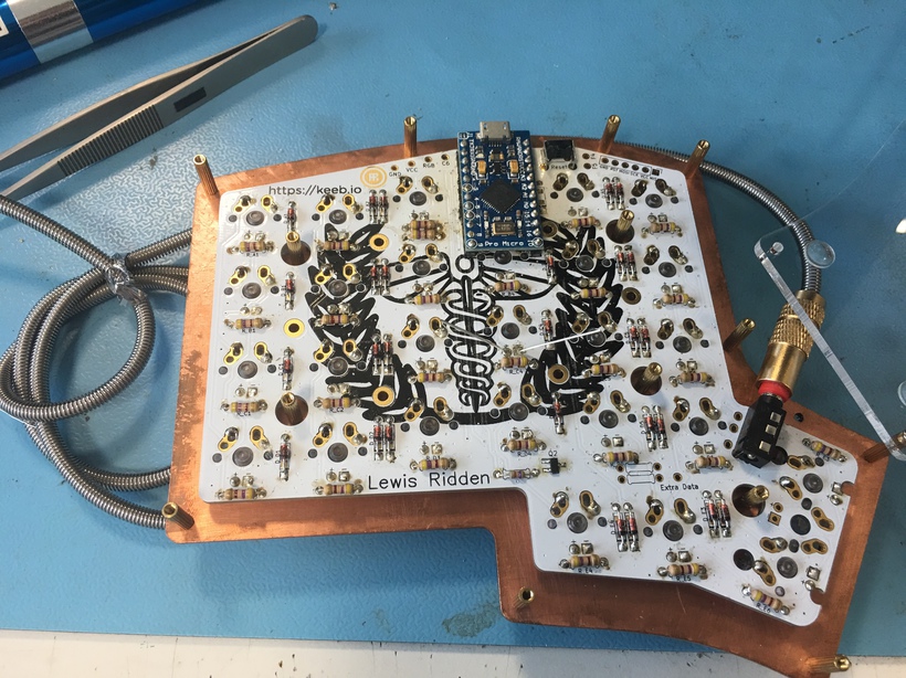
Now is a good place to note that as these boards were B-stock one came pre-soldered with a few reset switches, MOSFETs and other components (probably for testing). In particular the other board has SMD diodes and a MOSFET on which meant I doubled up on my order of diodes!
This process was repeated on the other board (flipped over).
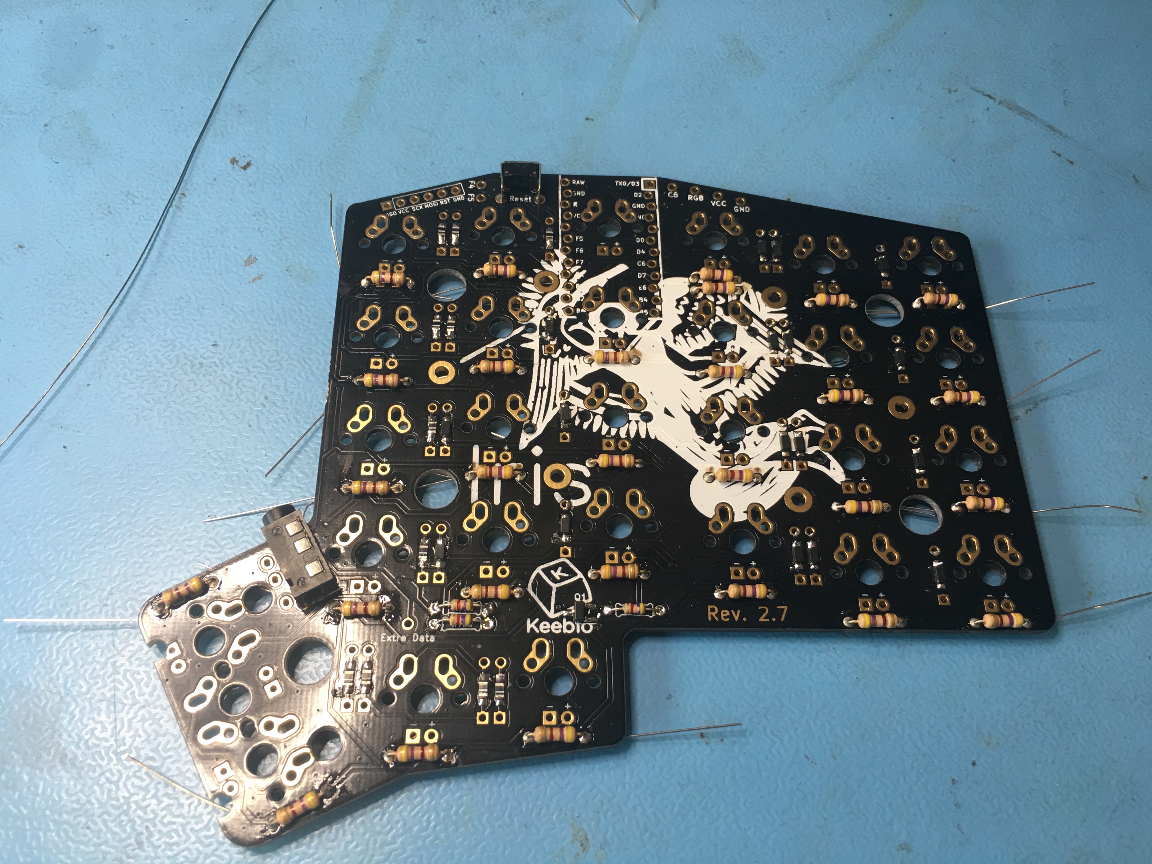
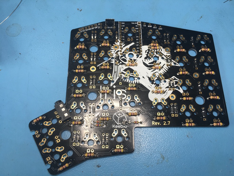
So that I had the following:
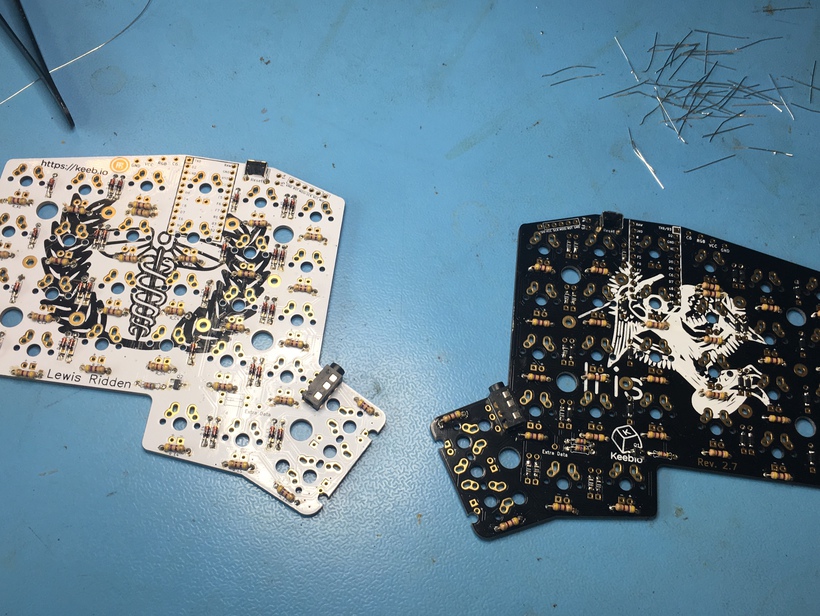
I also soldered on the micro-controller headers at this point.
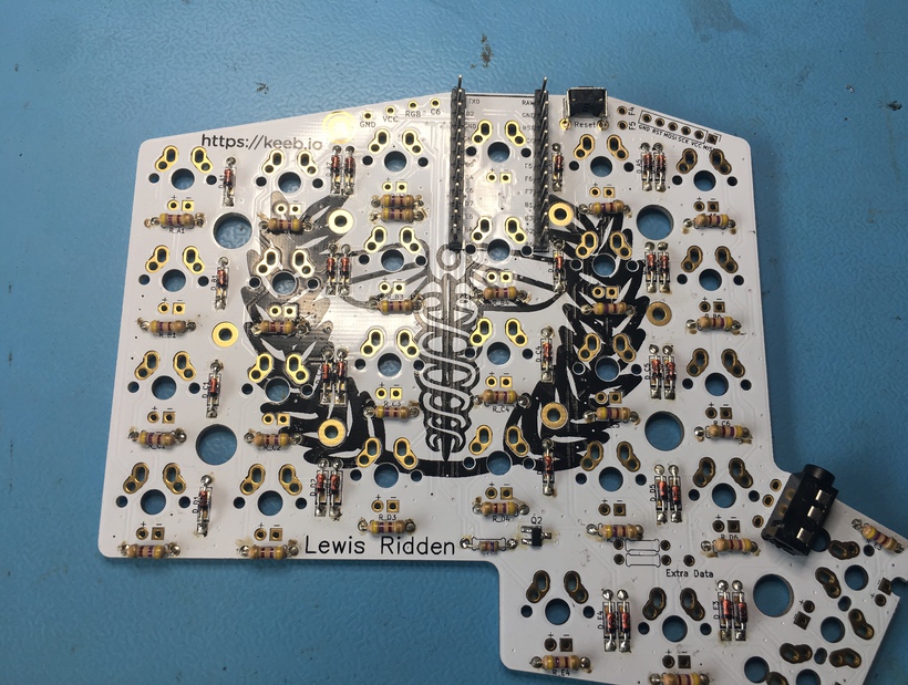
Mount the switches onto the plate and PCB.
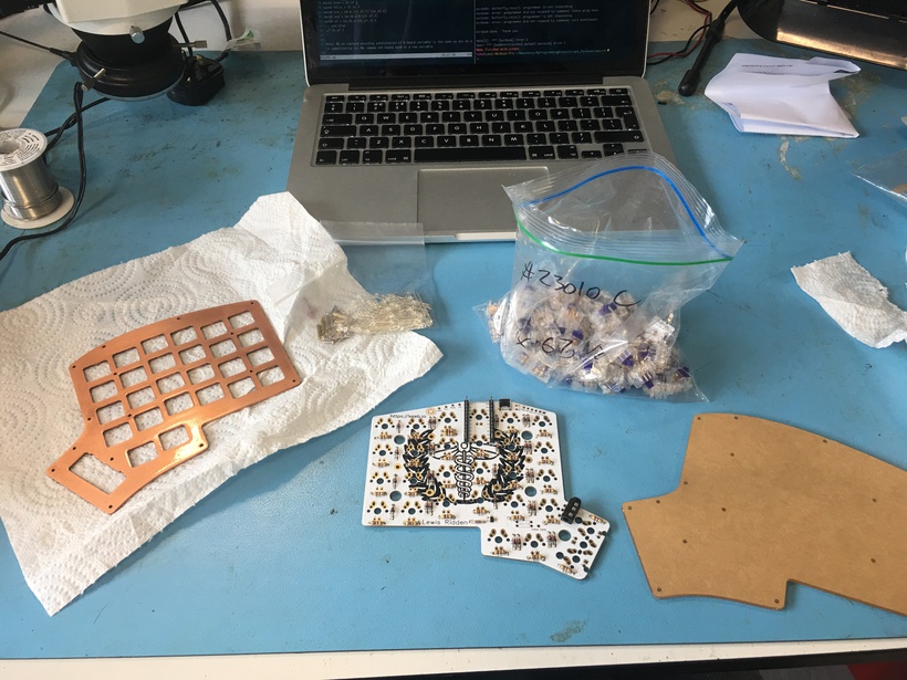
Now that the small components were soldered on it was time to mount the switches. It’s important to solder switches into the main corners of the plates and mount the PCB first so that you have a stable surface to solder the rest on.
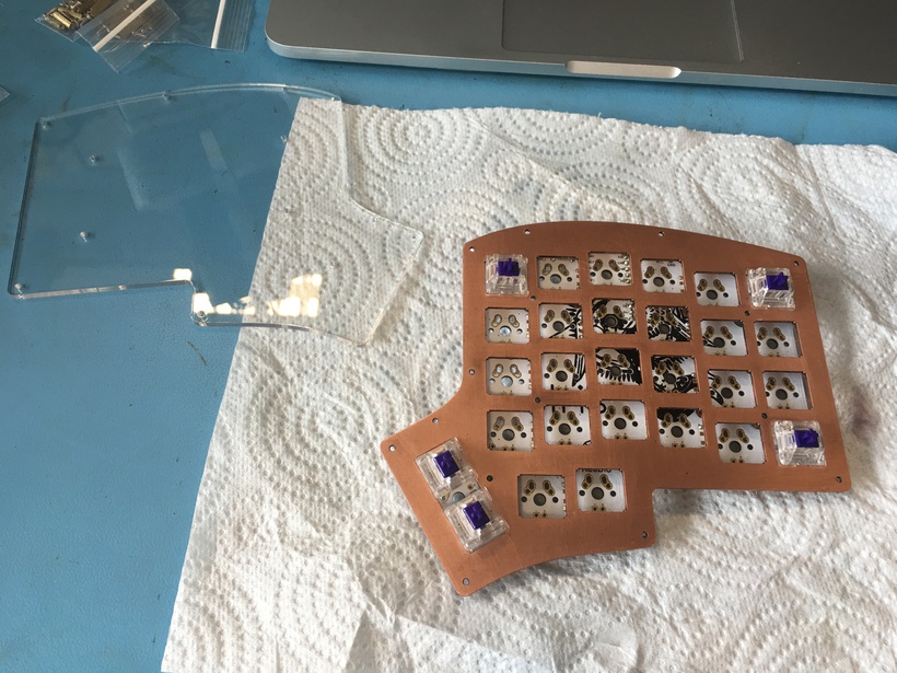
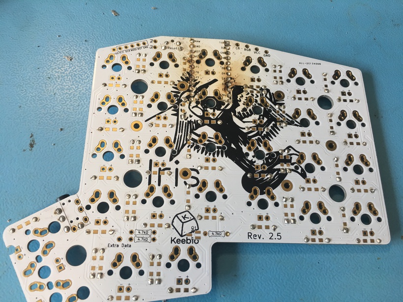
It was at this point that I realised not only that I had soldered the headers on the wrong way round, but also that I didn’t have enough clearance between the micro-controller and the acrylic base. At this point I used a heat gun to remove the headers and fit some smaller ones which ruined the finish in the process.
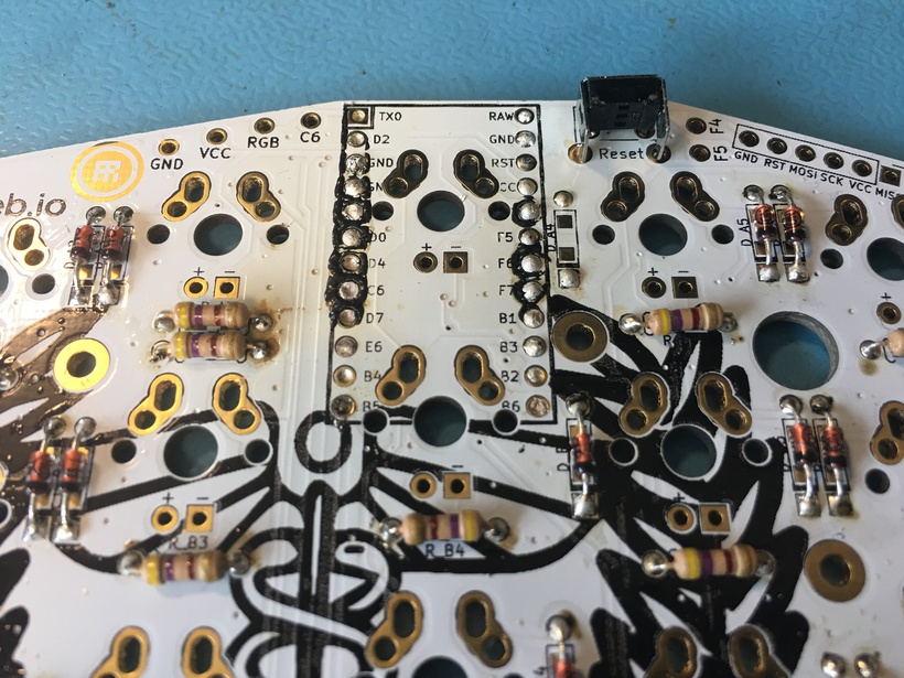
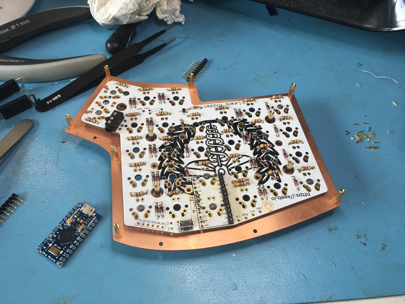
Before fitting the full set, I quickly assembled the other switch plate to see if it had the same problem, luckily it didn’t.
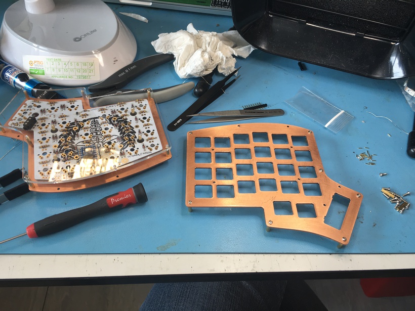
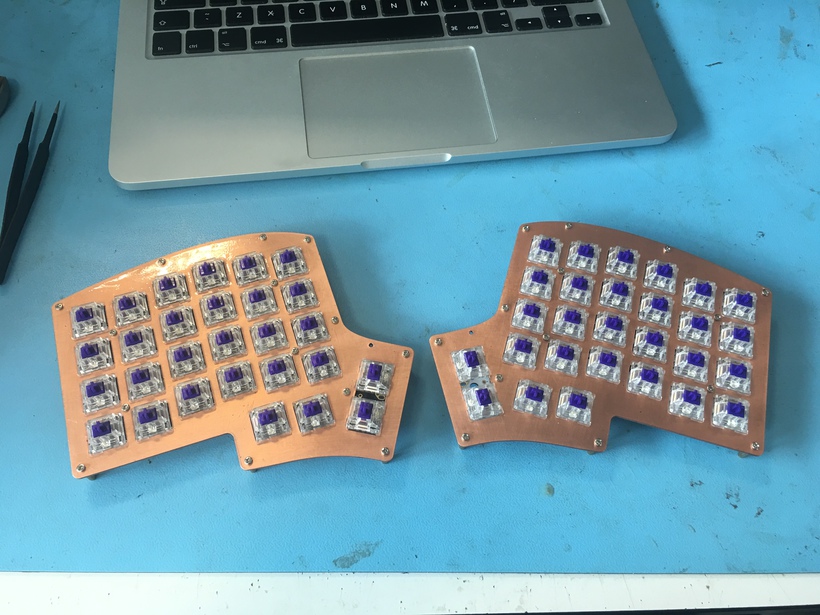
Lastly I soldered on the rest of the switches
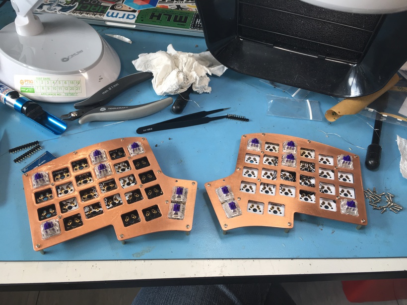
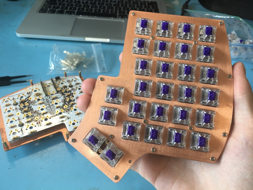
Solder the LEDs and micro controllers onto the PCBs
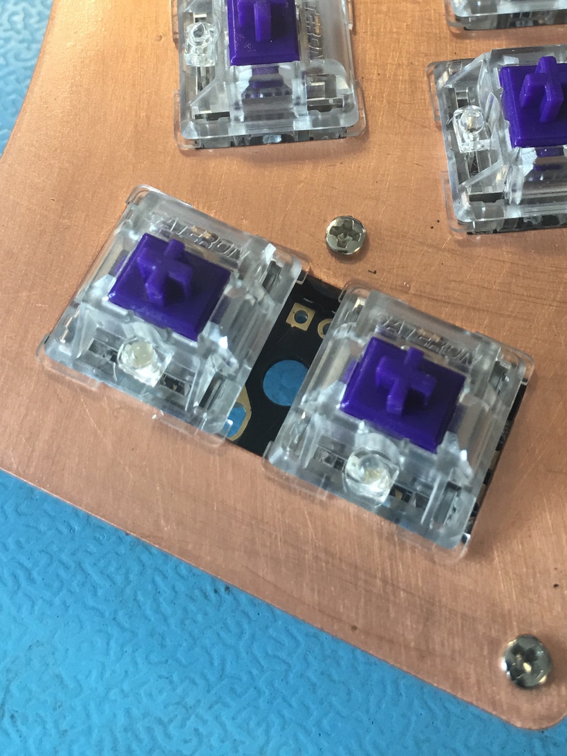
At this point it’s day 5 of the build and the end is in sight! At this point the remaining tasks were to solder on the last components and test that the keyboard worked. The switches supported through-hole LEDs which needed to be mounted and soldered in the same way as the resistors.
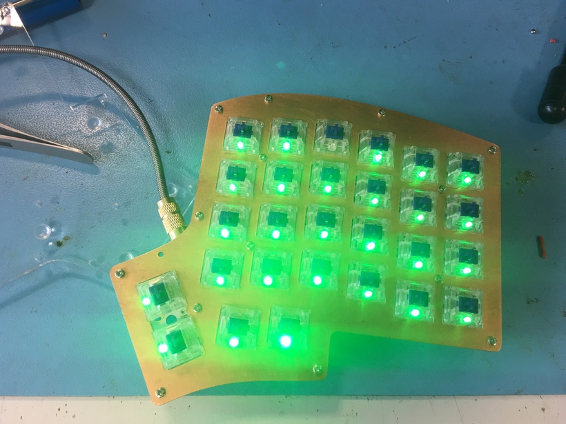
And they sit comfortably in each switch
Finally the micro-controllers were soldered onto the new headers. Luckily the burn isn’t too visible.
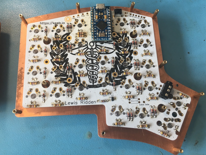
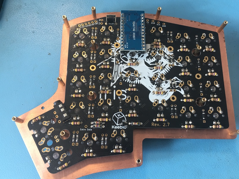
After assembly and screwing on the acrylic base the build was done! Luckily the firmware worked as expected too, however there were a few caveats which I cover in the Comments below.
Comments & Further Work
Comments
Overall the build was a success with caveats. The board (sort of) works and is pleasant to type on however there were several problems during the build and plenty of room for improvement. I am largely happy with the result however as there is a beauty in uniqueness of the build and the memories that come with it!
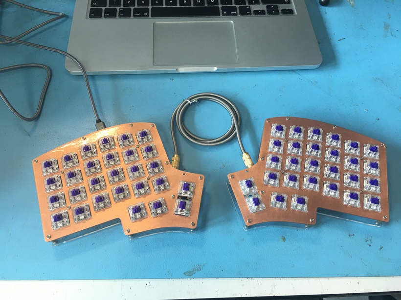
The build itself is very solid with the copper and acrylic base; there is no flex in the boards. The open design means the switch mounts are exposed however, so the board has a noticable clack when used. This isn’t a deep clack either, but rather rounded with accentuated highs. This was muted to a degree by rubber O-rings under the keycaps, however the sound is still prominent and I’m not convinced I’m a fan just yet. It measures in volume somewhere between the muted thunk of cherry MX clears and the thinner click of MX blues.
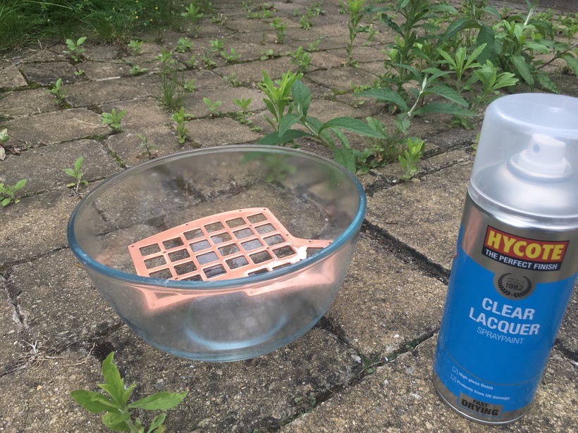
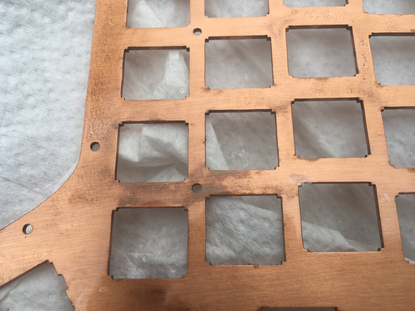
As for my lacquering skills there is plenty of room for improvement. I had never lacquered anything before, let alone a copper surface that is very sensitive to patina. Additionally the plates dried outside during one of the hottest summers on record and so the plastic layers cracked several times. The result was a bubbly and inconsistent finish. This took multiple attempts to get right, and multiple experiments to find the best way to prepare the copper. According to the internet white vinegar and salt is meant to be quite effective at removing patina however I found it was far too aggressive at removing the top layers of copper. This had long lasting effects as I couldn’t restore the copper to a patina-free point. Next I tried 99% strength Isopropyl alcohol which was much better at removing bad lacquer, cleaning the copper, and leaving no residue. I also ruined a Pyrex bowl when lacquering the plates. The result was barely worth the effort but I have received compliments about the professional quality of the finish, despite the patina on the undersides of the plates. If I were to work with untreated metals again, I would ensure they are treated professionally before use.
As with most custom builds the costs rack up quickly and so heavy emphasis was placed on testing components before fitting them. This caught 2 dud LEDs and no dead switches however 2 LEDs broke later in the build sometime between soldering and testing the boards. The modular nature of the build meant it was largely impossible to ensure all components worked together as expected until the last micro-controller was soldered on. Faith in my soldering is not ideal but necessary and falls into that uncomfortable space of problems that are fiddly to get right and outright unpleasant to adjust in small increments. This was noticeable when mounting the micro-controllers above LED solder points as I had to solder this whilst keeping the mount straight at a fixed height.
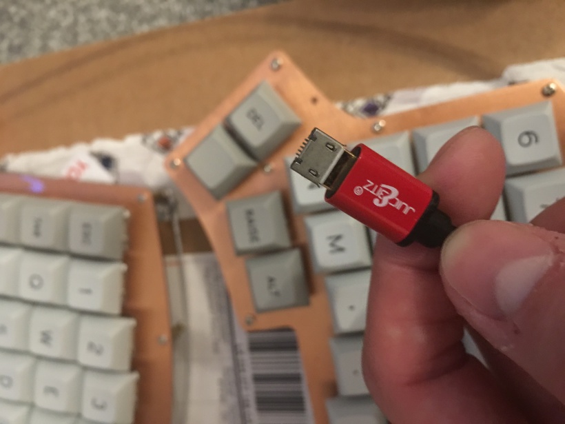
With the finishing posts in sight it was only fitting that more problems would come my way. Firstly, my custom keycaps were shipped from America and consequently got stuck in customs for 2 weeks. After arrival and installation I discovered an unfortunate feature of the Pro micro: the weak soldering on the USB header. Within 30 minutes of use the header (and traces) had snapped off! After futile efforts to recover the micro-controller, I ordered an Elite-C from SpaceCat design. The silver lining is that I get to try out the DFU bootloader, and future proof half of my keyboard with a USB C-type port; the obvious downsides are cost and the need to have 2 types of cable should I ever choose to swap the master micro-controller over.
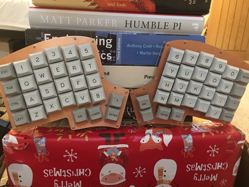
With all things said and done this project took quite a lot longer than I had planned. I gave myself a week to build the board, and write the software. Only one of these tasks was completed due to the delay on the keycap delivery, and micro-controller-based problems. It is possible to have worked on the software without caps however the week was up and I was going on holiday :-) This time didn’t account for months of research required and months to deliver the components but I consider that to be a constant factor in most builds of this scale. Despite this, I believe the build was a success by virtue of the fact the board is at work and ready to go; I just need to spend a lunchtime replacing the broken controller. As for user testing and firmware, I may write another post in the future.
For my first build this board represents a success. It is a high quality piece of kit and I suspect it will help my productivity substantially, if not minimising RSI. Admittedly I could have spent more time considering the ergonomic, stylistic, and practical matters but I’m leaving that to further work.
Further work
The base is finished but there is more work to be done! These odd jobs, some of which are not necessary, will improve the keyboard and (hopefully) my skills.
I’m not sold on the idea of using green LEDs to give an ‘oxidation effect’ as it contrasts too heavily with the copper, silver, and brass parts. Ideally the PCB would support 3-pin LEDs to vary the colour as needed but that wasn’t supported in the rev 2. I may replace the green LEDS with yellow ones to be consistent.
Additionally I never installed the LED under glow strip and I’m debating whether the build really needs it.
In order to maximise the ergonomic utility of this board I would like to add copper tents (like laser ninja’s) to the board so I can vary the angle of the board; ideally to an arbitrary degree but more realistically at fixed heights by screwing into the M2 fittings. If you’re reading this and you know of copper tents like these then please let me know!
At the time of writing, I have just received my replacement micro-controller but have not soldered it onto the PCB yet. As a result I haven’t used the board, or written my own firmware for it. The plan is to design and write my on Space Cadet QMK driver with Greek, logic, and LISP-inspired layers. This will help with accessing these symbols as unicode, for which support is increasing.
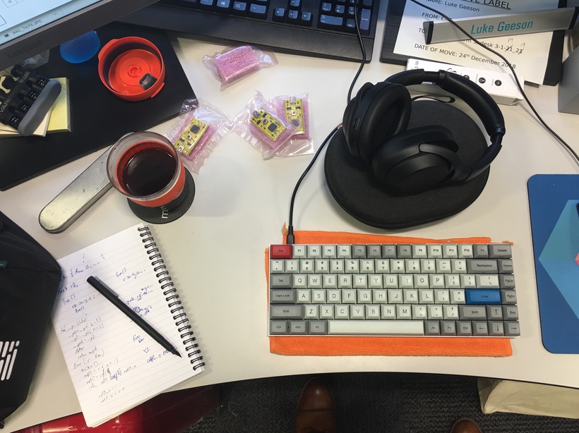
Once all is said and done this build was largely component based. If I make another keyboard I may build it from the ground up. That is, using spare Arm powered micro-controllers, custom wiring, custom cut cases, and bespoke firmware. I would learn more about the fundamental components of firmware and driver get to design a board from the ground up. This board would be portable (at 75% in size like the race 3) to work with my laptop and would fit into a mahogany case with a removable lid so I can use it on the go.
Acknowledgements
I’d like to thank Alastair Reid for his tips and discussions about keyboard builds over lunch in the early phases, and the many RSI jokes made in the office!
I’d like to thank Yiangos Yiangou for his help in sourcing the Iris PCB B-stock which is now out of circulation, and for his advice to look at laserboost for switch plates!
I’d like to thank Vasileios Laganakos for his recommendations to go with Signature Plastics for the keycaps. They top a great build!
I’d like to thank the folks at laserboost and Signature Plastics for their advice and help choosing switch plates and keycaps.
Last but not least I’d like to thank the folks in the hardware lab at work who helped me solder and debug my board.
Feel free to email me if you have any questions using [email protected]